

Tile / glazed-tile roofs
Roof hooks and rails matched to the tile profile and underlying structure. Preserve the weather seal and check rafter / purlin fixing.
rove on, power on
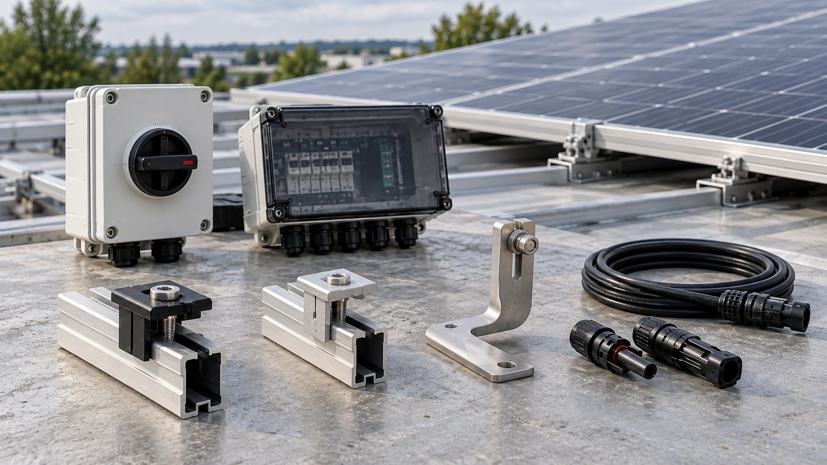
BOS & ACCESSORIES
Mounting, cabling, switching and protection, coordinated with your layout and electrical design.
Explore mounting & componentsMOUNTING SYSTEMS
The mounting arrangement follows the structure, terrain, wind and snow conditions, with waterproofing and maintenance access considered early.
Roof hooks and rails matched to the tile profile and underlying structure. Preserve the weather seal and check rafter / purlin fixing.
Clamps or brackets for the actual standing-seam or trapezoidal profile. Review pull-out resistance, corrosion interfaces and waterproof detailing.
Tilt frames with a ballast or anchored arrangement, selected around structural capacity, uplift, shading and roof access.
Above-ground ballast where driven foundations are unsuitable. Check bearing capacity, sliding and uplift.
Triangulated support frames for the chosen tilt. Pair the support geometry with a suitable foundation.
Frames fixed to engineered concrete bases, with foundation dimensions and anchor details set for site conditions.
A single-pile support arrangement, subject to geotechnical conditions, embedment and pull-out resistance.
A two-pile arrangement where layout and structural design call for a wider support base.
Moving structures selected around terrain, wind stow strategy, row spacing, drive power and maintenance requirements.
Support geometry and foundation type can be combined. The final arrangement follows the structural and geotechnical design.
CONNECTION ESSENTIALS
PV cables and matched MC4 connectors form the standard connection kit. Cable lengths, conductor sizes, voltage ratings and connector quantities follow the actual layout.
CONFIGURED FOR THE PROJECT
ONE COORDINATED EQUIPMENT LIST
We bring mechanical, electrical and installation requirements into the same configuration review.
Surface profile, structural condition, slope, available area, soil conditions and access.
Wind and snow design conditions, corrosion exposure, drainage and waterproofing approach.
String arrangement, voltage and current, cable routes and lengths, voltage drop, earthing and fault levels.
Fixings, mounting rails, cable and connector quantities, protection ratings and equipment interfaces.
Maintenance access, monitoring, future capacity and space for additional equipment.
A coordinated component schedule with ratings, quantities and connection / installation interfaces to review.
ROVON POWER
Share your roof or site layout, module selection and electrical requirements.